Mission
Delivering continuous renewable energy and clean water through innovative hydro-compression systems for communities worldwide.
2 Billion
90% efficiency
More than solar
No reliable power or water
Vision
A future of universal access to sustainable power and safe water, enabling resilient and thriving communities.
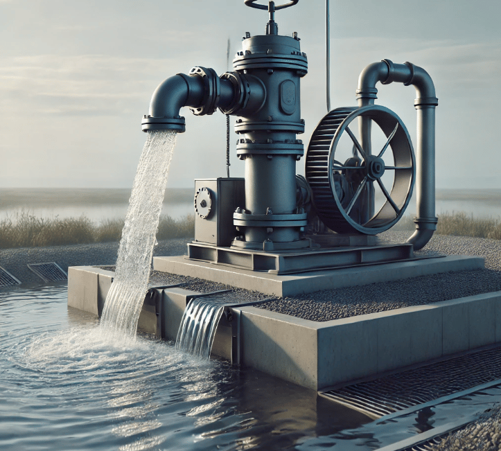
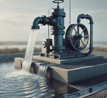
How It Works
Step 1: Air-filled tanks are lowered into water.
Step 2: Water pressure naturally compresses the air inside the tanks.
Step 3: Compressed air pushes water through small jets.
Step 4: Water jets hit a Pelton turbine, spinning a generator.
Step 5: Electricity is produced continuously; water flows back into the source with no pollution.
24/7 Renewable Power – Continuous energy, not weather dependent
Clean Water Access – Provides clean water for 5,000–10,000 people
Durable Design – Stainless or carbon-fiber tanks last 30–40 years
Low Maintenance – Simple mechanical parts, easily serviced locally
High Efficiency – Pelton turbines reach ~90% vs ~21% for solar
Pollution-Free – Zero emissions; clean water returned to the source
Cost Savings – No fuel, no batteries, minimal upkeep = fast ROI
Disaster-Ready – Reliable power and water during emergencies
Benefits
Materials
Carbon Fiber Composite
lightweight, ultra-strong, 40+ year lifespan
Any Waters
operates in fresh, salt, brackish, or dirty water
316L Stainless Steel
corrosion-resistant, 30+ year lifespan
Universal Hydro Power delivers continuous renewable electricity and clean water using durable, fuel-free hydro-compression systems.

Hi, why we need continous Power
think about it all the green energy solutions rely on intermittant power. Even Hydropower if the water source has a drought then we have a problem. I travel a lot toward Palm Springs California, there must be over 100 windmills out there. I have been there when there was a lot of wind and at least half of these were not turning. This is a lot of money spent and when there not running there is no revenue. They built a giant solar plant on the California border to Nevada. They are already shutting it down. Not profitable. So what we need is an endless supply of energy, and an endless supply of fuel.. I think we solved this issue. Whatch my video above I think it explains it pretty well. And look at the picture on the right. I think it explains how we could install these almost anywhere in the world. And it all the energy needs we keep having wouldn't it be nice if we could power small communities and data centers? Re-charge electric vehicles or create clean water for areas that need this. I truly believe we have a great solution. I would appreciate it if you check out the video. My team and I did extensive testing and also used AI to prove our calculations as well as built test items to prove it out. I was an electrician, and air conditioning technician. I converterd many machines with automation so they ran without assistance. I worked in many power generation places, coal and diesel powered. Of course the pollution is really high with this. I think this ansewers all the problems and the way it operates we need very little horsepower to create hundreds of horsepower to operate water pressured turbines and generate electricity 24/7 please email me for any questions we have a patent on the operation and am seeking a partner to develop a small scale system to prove it out and get it to the market. Thanks for reading this.
David Dean 909 267-4568
Innovate
Exploring renewable energy solutions for a sustainable future.
Sustainability
Energy
dave@universalhydropower.com
© 2024. All rights reserved.